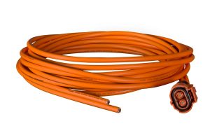
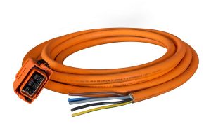
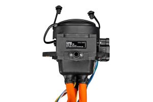
on-Board Charger
kompakt – effizient – leistungsstark
HV 800V/40A und LV 450/70A Version verfügbar
hoher Wirkungsgrad >94 %
AC Eingangsleistungsfaktor > 99 %
CCS/Typ2 Stecker kompatibel
AC Laden via Wallbox gemäß EC 61851 oder direkt
Flüssigkeitskühlung
Integriertes DC Laden mit EPLC Ladekontroller gemäß DIN SPEC 70121 und ISO 15118
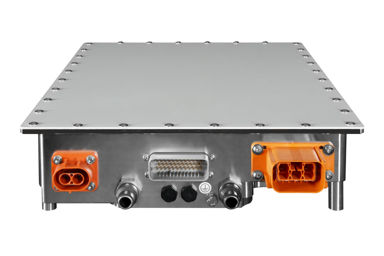
Unser on-Board Charger ist das weltweit erste fahrzeugseitige Ladegerät, das über Parallelbetrieb auf 176 kW Wechselstromladeleistung skaliert werden kann.
Durch sein schlankes Design, seine hohe Leistungsfähigkeit und Effektivität eignet sich das Ladegerät optimal für Nutzfahrzeuge, Busse, Baumaschinen, maritime Anwendungen und vieles mehr.
Die Möglichkeit des integrierten DC Ladens (gemäß DIN SPEC70121 und ISO 15118) zeichnet dieses Gerät aus und erweitert somit sein Einsatzspektrum.
– Charging power made in Germany –
Downloads
- Benutzerhandbuch
- User Manual
Mechanical Data
AC Input
DC Output
Safety
Standards
Environmental Requirements
Mechanical Data
| Housing | Aluminum | — |
| Weight | 15 | kg |
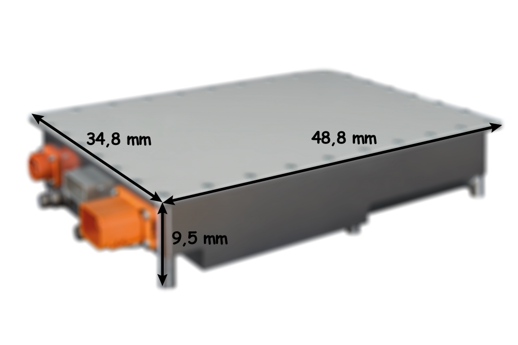
| Outline Dimensions | 488.4 x 347.8 x 95.2 | mm |
| IP protection | IP6k9k | — |
| Nom. Liquid Volume flow recommended | 8 | ltr/min |
| Min. Liquid Volume flow | 6 | ltr/min |
| Nom. Liquid Pressure drop | 45 | mbar@ 8 ltr/min see table below |
| Cooling Liquid Specification | min. 50% water → max. 50% antifrogen | — |
| Liquid Temperature Range | -30 to +50 | °C |
| Max. Liquid Temperature with power derating | 60 | °C |
| Liquid Output Temperature rise | < 5 | °C |
AC Input
| AC Input | Value | Units |
|---|---|---|
| Voltage range three-phase (Phase – Phase L1 → L2 → L3) | 360 – 480 | Vrms |
| Voltage range single-phase (L1 – N) | 200 – 250 | Vrms |
| Max. input current three – phase (each phase) | 32 | Arms |
| Input frequency | 45 – 65 | Hz |
| Power Factor (at three – phase) | > 99 | % |
| Starting Inrush Current | < 50 | A |
DC Output
| DC Output | OBC_22KW_800 | OBC_22KW_450 | ||
|---|---|---|---|---|
| Voltage range | 420 – 800 | VDC | 200 – 450 | VDC |
| Max Charging Current – three phase | 40 | A | 70 | A |
| Max Charging Power – three phase | 22 | kW | 22 | kW |
| Max Charging Current – single phase | 16 | A | 16 | A |
| Max Charging Power – single phase | 06. Jun | KW | 06. Jun | kW |
| Output Voltage ripple – three phase | ±2 | % | ±2 | % |
| Switch ON time | 5 | s | 5 | s |
| Output Voltage tolerance – three phase | ±1 | % | ±1 | % |
| Charging Mode | CCCV | — | CCCV | — |
| Output current tolerance – three phase | ±5 | % | ±5 | % |
| Output current ripple – three phase | ±2 | % | ±2 | % |
| Efficiency – three phase | >96 | % | >96 | % |
Safety
| Isolation Input/Output | DIN EN 61851-1:2012-01 | — | |
| Functional Safety | — | — | |
| AC overvoltage protection | Yes | — | |
| AC undervoltage protection | Yes | — | |
| AC overcurrent protection | Yes | — | |
| Open Circuit Protection | Yes | — | |
| Output Overcurrent protection | Yes | — | |
| Overtemperature | Yes | — | |
| Insulation Resistance | >5 | MΩ | |
| +24 V /+ 12 V reverse polarity protect | Yes | — | |
| Communication Failure protection | CAN timeout protection | — | |
| Interfaces at X3 | Description | ||
| 2x CAN Communication Interface IN and OUT | Internal CAN-BUS: CAN2.0B (Service CAN) External CAN-BUS: CAN2.0B (optional: SAE J1939, CANOpen) | ||
| Type 2 / CCS Inlet interface | according to DIN EN 61851-1:2012-01, 2x OBC shared pair operation on 1x 63 A Type 2 inlet 1x OBC on 1x 32 A CCS inlet | ||
| PLC Interface Optional | Communication according to DIN SPEC 70121:2012-08 | ||
| Inlet Lock Mechanism Control | Digital Inputs and Outputs to control and monitor Inlet Lock mechanism switchable to 12V and 24V (by SW parameter) | ||
| Electronic Supply voltage | 9-30 V @ 20 W max. power consumption | ||
| LED supply | Output for 3 LED’s (Green, Blue, RED) 5 V/5 mA | ||
| HVIL Loop | HVIL at control connector X3 max. +-48V to Chassis, max. 20mA Internal 22 Ohm resistor in series connected | ||
| Internal 22 Ohm resistor in series connected |
Standards
| DIN EN 61851-1:2012-01 | Electric Vehicle conductive charging system | EMI, Isolation Requirements |
|---|---|---|
| DIN EN 61851-21-1:2018-04 | EMI Requirements | |
| IEC 62196-2 | Type 2 AC Inlet | |
| IEC 62196-3 | CCS2 AC/DC Inlet | |
| SAE J1939 | Car Vehicle CAN Bus Standard | Optional |
| LV123 | Electrical Safety requirements | Optional |
| DIN SPEC 70121:2012-08 | CCS DC Charging | PLC Communication, Optional |
| DIN ISO 15118 | CCS DC Charging | Optional |
Environmental Requirements
| Environmental Requirements | Min | Max | |
|---|---|---|---|
| Ambient Temperature | -30 °C | +60 °C | |
| Storage Temperature | -40 °C | +85 °C | |
| Relative humidity | 5% | 95% | |
| Altitude | 0m | 3000 m |

